Digital Production Services Homepage Brown University Library Homepage Brown University Homepage

c u r i o

Imaging rare, unusual, and intriguing objects at the Brown University Library

Stereoscopy Digitized

May 21, 2015 by | 1 Comment

Last fall, the Brown University Library acquired a set of 100 stereographs made of Palestine in 1901. Stereographs are made using stereoscopy: a technique that involves creating the illusion of three-dimensional space using two-dimensional imagery. In photography, this means making two images that are just slightly offset from each other, and using a special viewer (a stereopticon) to look at both images at once. The illusion of depth between different spatial elements emerges as our brains attempt to reconcile these two different images into one, creating a (seemingly) three-dimensional scene.

Palestine-Full

One of the stereographs of Palestine, showing the two offset images that will eventually form the single three-dimensional image.

As is the case with most stereographs of this kind, these photographs are albumen prints that have been mounted onto thick card stock. Over time, many of these cards develop a curvature towards the mounted-print side. This makes it very difficult to digitize the images using a flatbed scanner; you can’t get even focus or lighting on a non-flat object, and it’s easy to rip the images or crack the emulsion of the photographs if any attempt is made to flatten the cards. This set of stereographs was no exception, and many of the cards had a distinct curve to them. To account for this, I digitized them using our reprographic camera so I could light them effectively and avoid the need to flatten the object altogether.

3dslidermaker

The next step was to create a three-dimensional image from each stereograph. There are a number of software applications that enable the user to merge two images from a stereograph into a single image that can be viewed as three dimensional using 3d glasses. I chose 3d Slide Maker, a freeware Macintosh application made by Mike Cook. This software lets the user upload the left and right sides of the stereograph, and then adjust the level of offset on the horizontal and vertical axes. It’s easy to view changes are you make them, so if you have a set of 3-D glasses you can check your work as you edit. This software also allows for additional imaging adjustments to correct any problems that creating the final 3-D image, or anaglyph, has caused in the image quality.

Once each new image was complete and exported, it was added to the collection of images. Each stereograph has three images associated with it: the front of the card; the back of the card (many of these have writing about the scene pictured on the front); and the 3-D anaglyph. If you have 3-D glasses, you can view the image below as a representation of what viewing the stereograph using a stereopticon might be like. You can also click here for an animated gif that shows the offset of the images.

Palestine033_03d

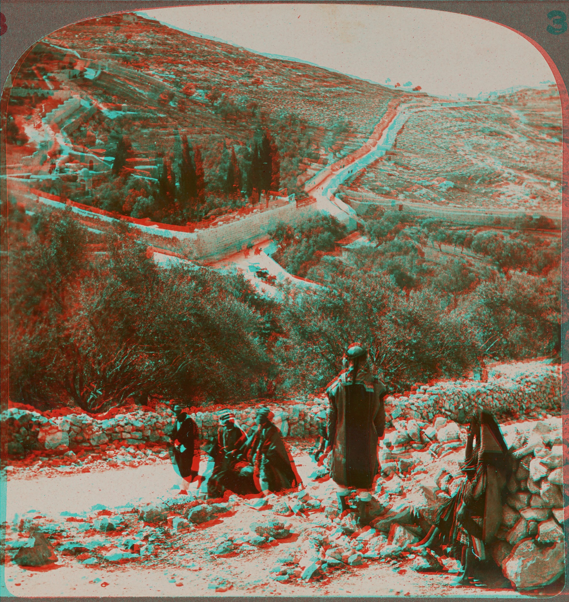
This collection will be displayed at Brown through 100 stereoscopic viewers in Fall 2016, curated by Ariella Azoulay and Issam Nassar, under the title Time Travelers in Palestine – Stereoscopic Journey.

Avoiding Moiré

March 25, 2014 by | 1 Comment

Because we photograph a great deal of prints and engravings, moiré patterning is an issue that we must consistently keep an eye out for. Moiré patterning often occurs during image capture; it can also happen if you’re viewing an image at a certain magnification, but this is easily addressed by changing the magnification. It’s when moiré patterning enters during image capture that you must address it immediately, since it’s difficult to remove without creating more image artifacts.

Moiré patterning happens when your subject has some type of regular pattern – in our case, this is usually regular lines in an engraving, but can also happen when photographing textures on paper or cloth that have a regular weave to them. When the regular pattern of the subject overlaps with the regular pattern of the image sensor, the moiré patterning is born. It’s usually seen as bands of color, or light and dark.

moire-problems

The two images above are examples of both kinds of moiré patterning. The image on the left, with the black-and-white pattern, happened due to image magnification. This image itself was fine, but viewing it at this magnification was problematic. The image on the right, however, shows moiré patterning that happened during the capture process. You can clearly see the bands of color that, rather than being a function of viewing the image, are actually present in the image itself.

Correcting the viewing problem is a non-issue; one must simply view the image on a different monitor or at a different magnification. Correcting the patterning that happens during capture is actually almost as simple: it’s all about the orientation of the original. Because moiré patterning is a function of the relationship between overlapping patterns, all we have to do to correct this is change that relationship; put another way, we have to change the alignment of the patterns. For this object (from our Rider Broadsides collection), I had been photographing all objects in the collection aligned as relatively straight verticals to the sensor. To correct the alignment, I simply tilted the image so it was crooked in the capture (it’s important that this isn’t a 90˚ tilt, but a more arbitrary tilt). This corrected the problem immediately. Below is the final image, as well as a detail of the most problematic area of the object.

moire-okay

It’s time to make the targets!

November 28, 2012 by | Comments Off on It’s time to make the targets!

It is standard practice here in Digital Production Services to include a reference target for tone and color reproduction in each digital image capture. The target is retained in the master TIFF file, and cropped out of the derivative file. Reference targets are used to achieve accurate color reproduction by providing visual references to known swatch color values directly within digital image captures. For our department’s newest digital camera-based system, we use an Image Science Associates target, which includes a focus/sampling-rate reference scale. For reflective (flatbed) scanning, FADGI Technical Guidelines for Digitizing Cultural Heritage Materials recommend that reference targets include a photographic gray scale, a color reference, and an accurate dimensional scale. The Kodak Q-13 is recommended for the gray scale and color reference. The Q-13 color reference includes a ruler along the top edge, but because its accuracy is debatable, we substitute with a dimensional scale generated in Adobe Illustrator.

Combined, streamlined targets can be created in-house by cutting and stacking the Q-13 strips. I create two versions, a standard 8” target and a 4” mini target, appropriate for postcard sized objects.

The Materials and tools used to create the combined targets are:

-Kodak Q-13 Color Separation Guide and Gray Scales
-Laminating Sheets
-Centimeter rules [printed]
-Scissors or Paper Cutter
-Exacto knife
-Ruler
-Bone folder

The technique I employ to create the 8” combined targets is to first cut two strips from each Q-13 color and greyscale target, and align them with the printed centimeter rule. Next, for purposes of color management, small marks should be made on particular greyscale patches. With an exacto knife, I notch the “A”, “M”, “B”, and 19 densities.

The mini-target is created by cutting down the full size targets. Include a subset of the greyscale patches (I use A, 1, 2; 6, M, 8; 15, B, 17; 19), and notch the greyscale “A”, “M”, “B”, and 19 densities.
Carefully align all Q-13 segments in the order shown, and pencil in the creation date on the back of each target.

Begin the final stage of assembly by cutting laminating sheets into 4” and 2” widths. Place the target strips and dimensional reference on top of the 4” strip. Place the 2” laminate strip on top of the dimensional reference, making sure to leave the Q-13 strips exposed. Use the bone folder to increase adhesion. By making diagonal cuts as shown, the remaining laminate material below the dimensional reference will serve as a “handle” and will allow the target to be positioned without touching the Q-13 densities directly.

Even with careful handling, reference targets become soiled over time and need to be replaced on a routine basis, especially if they are used regularly. The targets are also prone to fade, and therefore should be stored away from direct light sources.


Photography: Lindsay Elgin